

Welding Symbols Explained: A Practical Guide to ISO and AWS Drawings
- 1. What Are the Welding Symbols?
- 2. What Information Do Welding Symbols Convey?
- 3. Components of a Welding Symbol
- 4. Some Essential Aspects of Welding Symbols
- 4.1. Basic Welding Symbol Reference Chart
- 4.2. Difference Between Fillet Weld Leg Length and Throat Thickness
- 4.3. Weld Symbol Position
- 4.4. Groove Weld Symbols
- 5. Supplementary Welding Symbols
- 6. How to Read Welding Symbols on Engineering Drawings (6 Steps)
- 7. Welding Symbol Standards
- 7.1. TCVN 1691:1975
- 7.2. ISO 2553
- 7.3. AWS A2.4
- 7.4. Comparison of ISO 2553 and AWS A2.4 Welding Symbols
- 8. Common Mistakes When Reading Welding Drawings
- 9. Need Mechanical Fabrication and Welding Services?
A triangle on a fabrication drawing indicates a fillet weld. But which side of the joint needs welding, and how large should the weld be? This guide from An Thanh Tech explains how to read welding symbols under ISO 2553 and AWS A2.4, identify the arrow side, and distinguish fillet weld leg length from throat thickness.
Welding symbols are graphical representations on engineering drawings that specify weld types, locations, dimensions, and other requirements. TCVN, ISO 2553, and AWS A2.4 each have their own conventions for symbol placement, reference lines, arrows, and weld parameters.
his guide explains common welding symbols, fillet weld dimensions, supplementary markings and the differences between ISO 2553 and AWS A2.4.
1. What Are the Welding Symbols?
Welding symbols on engineering drawings are standardized graphical representations used to specify weld types, locations, dimensions, and fabrication requirements. In mechanical engineering, correctly interpreting these symbols helps engineers communicate design requirements accurately and minimize errors during fabrication, assembly, and quality inspection.
The most commonly used standards include:
- TCVN 1691:1975
- ISO 2553
- AWS A2.4
Before reading a drawing, engineers and welders must identify the applicable standard, as ISO and AWS differ significantly in their conventions for the arrow side and weld dimensions (e.g., a and z).
2. What Information Do Welding Symbols Convey?
A standard welding symbol provides five key types of information:
- Weld Type: Fillet welds, V-groove welds, U-groove welds, spot welds, etc.
- Weld Location: Arrow side or other side of the joint.
- Weld Dimensions: Leg length, throat thickness, and penetration depth.
- Weld Length and Pitch: Continuous, intermittent, or staggered welds.
- Supplementary Requirements: Field welding, all-around welding, and flush weld finishing.
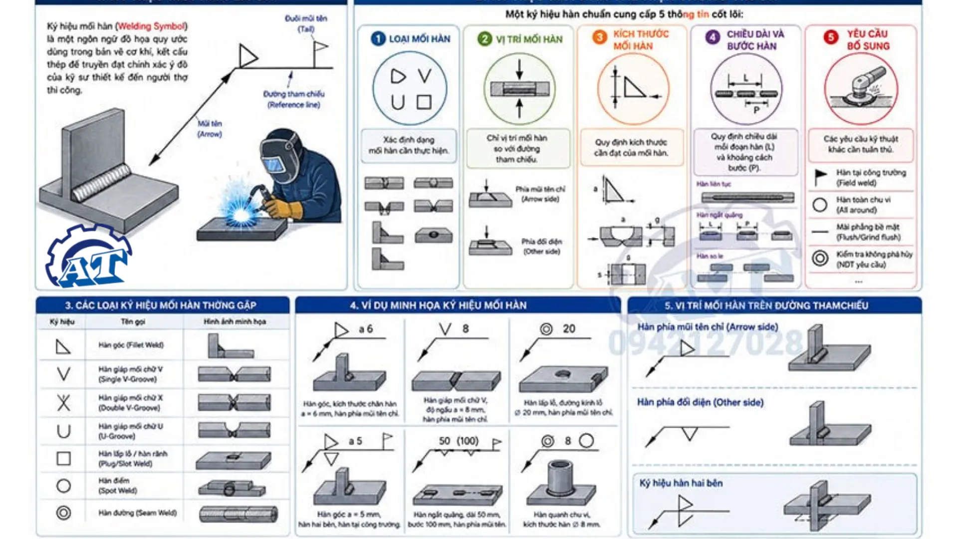
Welding Symbols on Engineering Drawings: Detailed Guide & Standard Reference Chart
3. Components of a Welding Symbol
According to international standards such as AWS A2.4, a complete welding symbol consists of the following components:
- Reference Line: A horizontal line serving as the main reference axis. It is a mandatory component.
- Arrow: A bent line extending from the reference line and pointing to the required weld location on the drawing.
- Weld Symbol: A geometric shape (triangle, V-shape, parallel lines, etc.) indicating the weld type. It is placed above or below the reference line.
- Supplementary Symbol: Additional symbols such as a flag (field weld), a circle (all-around weld), or contour symbols indicating the required weld profile.
- Tail: Located at the end of the reference line, it specifies welding standards, procedures (WPS), processes (TIG, MIG, MAG), or material requirements. It may be omitted when no additional information is required.
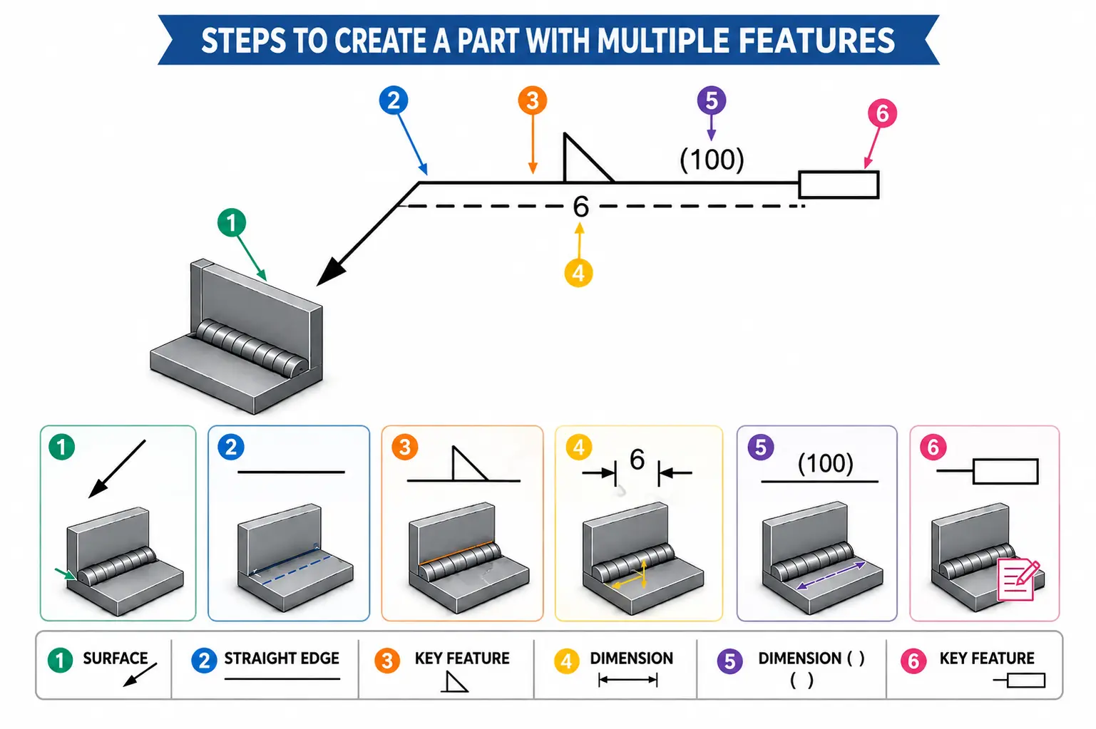
Components of a welding symbol
4. Some Essential Aspects of Welding Symbols
4.1. Basic Welding Symbol Reference Chart
The following table lists the most common weld types found on fabrication drawings:
| Weld Type | Symbol Shape | Practical Application |
|---|---|---|
| Fillet Weld | Right-angle triangle (△) | Joining two perpendicular components, such as frames and brackets. |
| Square Groove Weld | Two parallel vertical lines ( | |
| V-Groove Weld | V-shape (V) | Butt welding two plates with both edges beveled to form a V-shaped groove. |
| Bevel Groove Weld | Half-V shape | Only one plate edge is beveled, while the other remains square. |
| U-Groove Weld | U-shape (U) | Used for thick steel plates with U-shaped edge preparation. |
| J-Groove Weld | Half-U shape | A J-shaped groove is prepared on one plate while the other remains square. |
| Spot Weld | Small circle (O) | Resistance spot welding of sheet metal components. |
| Stud Weld | Circle with a cross | Used for welding bolts or studs onto a surface. |
*Fillet Weld: Fillet welds are among the most commonly used weld types in structural steel fabrication and mechanical engineering.
4.2. Difference Between Fillet Weld Leg Length and Throat Thickness
Understanding these two dimensions is essential to achieving the required weld strength:
- a (Throat Thickness): The height of the theoretical triangle representing the fillet weld. This dimension is commonly designated by a under ISO standards.
- z (Leg Length): The length of either perpendicular side of the fillet weld's theoretical triangle. Both ISO and AWS use this dimension, although AWS generally uses leg length as the default.
Quick Conversion:
z = a × √2
For example, an a5 weld is approximately equivalent to a z7 weld.
4.3. Weld Symbol Position
- Single-Sided Fillet Weld: The triangular weld symbol is placed on one side of the reference line.
- Double-Sided Fillet Weld: Two triangular weld symbols are positioned on opposite sides of the reference line.
4.4. Groove Weld Symbols
Groove welds are used to join components positioned in the same plane, typically in butt joints.
- V-Groove / X-Groove Welds: Commonly used for medium-thickness steel plates. A V-groove indicates welding from one side, while an X-groove (two opposing V-shaped grooves) indicates welding from both sides.
- U-Groove / J-Groove Welds: Commonly used for thick steel plates. U-shaped groove preparation helps reduce welding consumable consumption and thermal distortion compared with wider V-grooves.
5. Supplementary Welding Symbols
- All-Around Weld: Represented by a small circle at the intersection of the arrow and reference line. It indicates that the weld must extend continuously around the entire perimeter of the component, such as when welding a pipe to a flange.
- Field Weld: Represented by a flag symbol, indicating that welding must be performed on-site rather than in the fabrication workshop.
- Flush Contour: Represented by a straight horizontal line above the basic weld symbol. It requires the weld surface to be ground or finished flush.
- Convex / Concave Contour: These symbols specify the required weld surface profile, indicating whether the finished weld should be convex or concave.
6. How to Read Welding Symbols on Engineering Drawings (6 Steps)
Follow these six steps to avoid errors during fabrication:
- Identify the Applicable Standard: Check the drawing's title block to determine whether it follows TCVN, ISO, or AWS.
- Identify the Reference Line and Arrow: Determine the exact location indicated by the arrow.
- Determine the Welding Side: Check whether the symbol is positioned above or below the reference line to identify the arrow side or other side.
- Identify the Weld Type: Refer to the symbol chart to determine whether it specifies a fillet weld, V-groove weld, spot weld, etc.
- Read the Weld Dimensions: Cross-sectional dimensions (a, z, and penetration depth) are generally indicated to the left of the weld symbol, while weld length and pitch are shown on the right.
- Check Supplementary Symbols: Look for a flag (field weld), a circle (all-around weld), or additional requirements specified in the tail.
7. Welding Symbol Standards
7.1. TCVN 1691:1975
This is an older Vietnamese standard with relatively straightforward welding symbol conventions. However, fabrication drawings for export projects and large industrial projects increasingly adopt ISO or AWS standards instead of relying exclusively on TCVN.
Always check the drawing's title block before starting fabrication.
7.2. ISO 2553
ISO 2553 is one of the most widely used international welding standards.
Its key feature in System A is the use of two parallel reference lines: one continuous line and one dashed line.
- Symbol on the continuous line: Indicates welding on the arrow side.
- Symbol on the dashed line: Indicates welding on the opposite side.
7.3. AWS A2.4
AWS A2.4 is the welding symbol standard developed by the American Welding Society. It is widely used in oil and gas projects and structural steel fabrication worldwide.
Unlike ISO 2553 System A, AWS uses only one continuous reference line.
- Symbol below the reference line: Indicates welding on the arrow side.
- Symbol above the reference line: Indicates welding on the opposite sides
7.4. Comparison of ISO 2553 and AWS A2.4 Welding Symbols
The differences between these two standards are one of the most common causes of confusion, accounting for over 80% of errors when reading and interpreting international fabrication drawings:
| Feature | ISO 2553 (System A) | AWS A2.4 |
|---|---|---|
| Reference Line | Double lines (one continuous and one dashed) | Single continuous line |
| Arrow Side | Symbol placed on the continuous line | Symbol placed below the reference line |
| Other Side | Symbol placed on the dashed line | Symbol placed above the reference line |
| Fillet Weld Dimensions | Explicitly specified as a (throat thickness) or z (leg length) | Leg length is generally the default dimension |
| Symbol Tail | Closed forked tail when additional information is specified | May be open or omitted when not required |
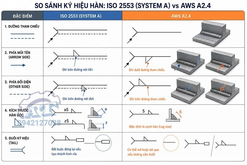
Comparison of iso 2553 and aws a24 welding symbols
8. Common Mistakes When Reading Welding Drawings
- Confusing the Arrow Side and Other Side: Welders familiar with AWS conventions (symbols below the reference line indicate arrow-side welding) may mistakenly apply the same rule to ISO drawings, resulting in welding on the wrong side of the component.
- Confusing Dimensions a and z: A drawing specifying a5 requires a throat thickness of 5 mm, equivalent to a leg length of approximately 7 mm. However, producing a z5 weld instead results in a throat thickness of only approximately 3.5 mm, reducing the structural load-bearing capacity.
- Overlooking the Tail Symbol: Ignoring welding process requirements specified in the tail, such as TIG welding to minimize distortion, may lead to using an unsuitable process such as MIG welding, potentially compromising product quality.
- Confusing Intermittent Weld Configurations: A drawing specifying staggered intermittent welding may be incorrectly interpreted as chain intermittent welding, resulting in an incorrect weld arrangement.
9. Need Mechanical Fabrication and Welding Services?
Interpreting welding symbols and estimating material requirements in accordance with technical standards such as ISO 2553 and AWS A2.4 requires more than just drawing-reading skills. It also demands specialized knowledge and practical experience in mechanical fabrication. Even a minor mistake in identifying weld types, dimensions, or locations can lead to material discrepancies, additional labor costs, production delays, or even complete rework.
Choosing a qualified mechanical fabrication partner with strong technical expertise, in-depth knowledge of welding standards, and extensive practical experience is therefore essential.
At An Thanh, our engineering team provides:
- Accurate verification and interpretation of welding symbols and dimensional tolerances on engineering drawings.
- Technical consultation on material selection and welding procedure optimization (WPS).
- Custom mechanical fabrication based on engineering drawings, including structural steel fabrication, sheet metal bending, CNC laser cutting, and precision welding.
Contact us and send us your engineering drawings today to receive technical consultation and a competitive fabrication quotation.
Related News

17/11
2026
In laser metal cutting, product accuracy depends not only on machine power and cutting speed but also on various other technical parameters. One of the key factors that is often discussed is Kerf Width, which refers to the width of the cut produced by the laser.
What is kerf width? Why does it affect machining quality? And how can this parameter be controlled to minimize dimensional deviations and optimize production efficiency? Let's explore these questions in the following article.

14/11
2026
Mechanical engineering manufacturing is one of the fundamental engineering disciplines driving the development of modern industry. Almost every product and piece of equipment used in manufacturing, from industrial machinery and automotive components to agricultural equipment and everyday consumer goods, relies on mechanical manufacturing technologies at some stage of its production.

09/11
2026
Knowing how to clean and store tie-down straps properly prevents webbing wear, stops ratchet rust, and ensures safe cargo transport. Follow these 3 simple steps to wash, dry, and store your straps for maximum longevity.

07/11
2026
Think all industrial greys look the same? Place RAL 7032 (Pebble Grey) next to RAL 7035 (Light Grey), and the contrast between warm beige-grey and bright silver-grey is unmistakable. Explore their exact color codes, powder coating specs, and ideal applications below to choose the right finish.
View more