

What Is Kerf Width (Laser Cutting Kerf)? How Does It Affect Machining Quality?
- 1. What Is Kerf Width?
- 2. Characteristics of Kerf Width in Laser Cutting
- 3. Factors Affecting Kerf Width in Laser Cutting
- 3.1. Laser Power
- 3.2. Cutting Speed
- 3.3. Focus Position
- 3.4. Material Type and Workpiece Thickness
- 3.5. Assist Gas and Gas Pressure
- 4. How Does Kerf Width Affect Machining Quality?
- 5. How to Calculate and Compensate for Kerf Width in Laser Cutting
- 6. Methods for Controlling Kerf Width to Improve Machining Quality
- 6.1. Optimize Cutting Parameters
- 6.2. Inspect and Maintain the Laser Cutting Head
- 6.3. Perform Test Cuts Before Mass Production
- 7. Frequently Asked Questions About Kerf Width (FAQ)
- 8. Conclusion
In laser metal cutting, product accuracy depends not only on machine power and cutting speed but also on various other technical parameters. One of the key factors that is often discussed is Kerf Width, which refers to the width of the cut produced by the laser.
What is kerf width? Why does it affect machining quality? And how can this parameter be controlled to minimize dimensional deviations and optimize production efficiency? Let's explore these questions in the following article.
1. What Is Kerf Width?
Kerf Width refers to the width of the material removed during the laser cutting process, measured as the distance between the two edges of the cut after the material has been separated.
Simply put, when a focused laser beam hits the metal surface, concentrated thermal energy heats a small area, causing the material to melt or vaporize. Assist gas then blows the molten or vaporized material away from the cutting zone, creating a kerf of a specific width.
The distance between the two sidewalls of this cut is known as Kerf Width.
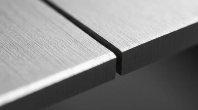
What is Kerf Width?
In laser cutting, Kerf Width is typically measured in millimeters (mm) or micrometers (µm), depending on the material thickness and machining requirements.
2. Characteristics of Kerf Width in Laser Cutting
Some of the key characteristics of laser cutting kerf width include:
- Dependent on the focal spot size: The diameter of the laser beam at the focal point significantly affects the width of the material area being processed.
- Varies with machining parameters: Laser power, cutting speed, focal position, and assist gas pressure can all affect Kerf Width.
- May vary across the material thickness: The kerf width at the top and bottom surfaces of a metal sheet may differ, resulting in edge taper.
- Affects finished part dimensions: Without proper kerf compensation, the actual dimensions of the cut part may deviate from the design specifications.
Importantly, Kerf Width is not a fixed parameter that applies to all laser cutting machines. Its value must be determined based on the material type, workpiece thickness, and actual machining conditions.
3. Factors Affecting Kerf Width in Laser Cutting
Laser cutting kerf width is influenced by several technical factors. Understanding each of these factors helps operators better control the machining process and maintain consistent cutting quality.
3.1. Laser Power
Laser power determines the amount of energy delivered to the processing area per unit of time.
When other conditions remain constant, increasing laser power can increase the heat input into the material, causing the molten zone to expand and Kerf Width to increase. Conversely, if the laser power is insufficient, the material may not be completely penetrated, resulting in incomplete cuts or interrupted cutting lines.
Therefore, laser power must be selected according to the material type, workpiece thickness, and cutting speed.
3.2. Cutting Speed
Cutting speed refers to the rate at which the laser cutting head moves across the material surface.
This parameter is directly related to the amount of thermal energy applied per unit length of the cutting path.
- Excessively low cutting speed: More heat accumulates in the material, potentially expanding the molten zone and increasing the kerf width.
- Excessively high cutting speed: The energy delivered per unit length may be insufficient, resulting in incomplete penetration, dross formation, or uneven cut edges.
- Optimal cutting speed: Helps maintain a stable cutting process, minimize material distortion, and improve edge quality.
*It is important to note that the effect of cutting speed also depends on laser power, material properties, and assist gas conditions.
3.3. Focus Position
The focus position determines where the laser beam achieves its highest energy density.
If the focal position is not properly adjusted, the size of the heat-affected area may change, causing Kerf Width to vary throughout the material thickness.
In sheet metal laser cutting, properly adjusting the focal position helps optimize kerf geometry, improve cut wall perpendicularity, and minimize edge taper.
3.4. Material Type and Workpiece Thickness
Different materials have different characteristics in terms of energy absorption, thermal conductivity, melting temperature, and oxidation behavior.
For example:
- Carbon steel has different cutting characteristics compared to stainless steel.
- Aluminum has high thermal conductivity, which affects heat distribution in the processing zone.
- Copper and certain copper alloys have relatively high laser reflectivity, requiring appropriate machining conditions.
Additionally, as material thickness increases, maintaining sufficient energy and removing molten material throughout the entire kerf depth become more challenging.
Therefore, a single Kerf Width value cannot be applied universally to all material types and thicknesses.
3.5. Assist Gas and Gas Pressure
Assist gas helps remove molten material from the kerf and also contributes to the cutting process, depending on the type of gas used.
Common assist gases include:
- Oxygen (O₂): Can participate in oxidation reactions to support the cutting of carbon steel.
- Nitrogen (N₂): Commonly used to minimize oxidation on cut surfaces, particularly when processing stainless steel.
Improper gas pressure can prevent molten material from being effectively expelled, resulting in dross formation and affecting kerf geometry and cut edge quality.
4. How Does Kerf Width Affect Machining Quality?
Kerf Width directly affects dimensional accuracy, cut edge quality, part fit-up, and material utilization. Its impact can be explained as follows:
- Dimensional Accuracy: Without proper Kerf compensation, the dimensions of the finished parts may deviate from the design specifications, particularly for components requiring tight tolerances.
- Hole and Slot Accuracy: If the Kerf Width is too large relative to the required feature dimensions, hole diameters may exceed the design specifications, slots may become wider than intended, and thin-walled components may have dimensional inaccuracies.
- Cut Edge Quality: Unstable kerf conditions can be associated with defects such as rough cut edges, metal dross formation, inconsistent cutting lines, inclined or tapered cut walls, and an enlarged heat-affected zone (HAZ).
- Part Fit-Up and Assembly Accuracy: Kerf deviations can cause bolt holes, mating slots, or male and female components to fall outside the required dimensions, resulting in excessive gaps or positional misalignment during assembly.
- Material Waste: The wider the Kerf Width, the more material is removed during cutting. This increases raw material waste, affects production costs, and reduces the efficiency of part arrangement on the material sheet (nesting).
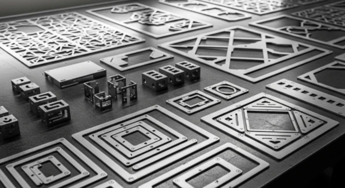
How Does Kerf Width Affect Machining Quality?
*Note: The goal should not be to minimize Kerf Width at all costs, but rather to maintain a consistent and stable cutting width. This requires optimizing laser power, cutting speed, focal position, and assist gas conditions to ensure overall machining quality.
5. How to Calculate and Compensate for Kerf Width in Laser Cutting
To ensure that finished parts meet the required dimensional specifications, kerf compensation must be applied during toolpath programming.
5.1. Kerf Width Calculation Formula
In principle, Kerf Width can be determined as follows:
- For External Cuts (Outside Cuts – Positive Features): Measure the dimensions of the cut-out material piece.
Kerf Width = Design Dimension − Actual Dimension:
Example: A 20 mm square is designed and cut. After cutting, its actual measured dimension is 19.85 mm.
→ Kerf Width = 20 − 19.85 = 0.15 mm
- For Internal Cuts (Inside Cuts – Negative Features): Measure the dimensions of the opening in the workpiece.
Kerf Width = Actual Hole Dimension − Design Hole Dimension
Example: A circular hole with a designed diameter of 10 mm is cut. After cutting, its actual measured diameter is 10.15 mm.
→ Kerf Width = 10.15 − 10 = 0.15 mm
*Note: These calculations are provided for reference purposes only. In actual production, test cuts should be performed and measured using appropriate measuring instruments to determine the actual Kerf Width under specific machining conditions. The measurement results should also account for the influencing factors discussed in Section 3.
5.2. Kerf Compensation Principles
For a cutting path with a Kerf Width of K, the cutting path centerline must be offset by a distance equal to K/2 to compensate for the material removed during cutting.
- For external contours: The toolpath should be offset outward to maintain the required finished part dimensions.
- For internal contours: The toolpath should be offset inward to ensure that holes or slots meet the specified design dimensions.
6. Methods for Controlling Kerf Width to Improve Machining Quality
To maintain consistent laser cutting quality, a Kerf Width control process should be established, covering everything from parameter setup to finished product inspection.
6.1. Optimize Cutting Parameters
Laser power, cutting speed, focal position, and gas pressure should be configured according to the machine manufacturer's recommendations and the material properties.
Avoid arbitrarily increasing laser power or reducing cutting speed, as these adjustments may alter the heat-affected zone and negatively impact kerf quality.
6.2. Inspect and Maintain the Laser Cutting Head
The cutting head, focusing lens, and nozzle all affect laser beam quality and assist gas delivery.
Regular cleaning, inspection, and component replacement when necessary help maintain stable machining conditions and consistent cutting performance.
6.3. Perform Test Cuts Before Mass Production
Before starting large-scale production, representative test cuts should be performed to evaluate the following:
- Kerf width.
- Actual part dimensions.
- Cut wall perpendicularity.
- Dross formation.
- Cut edge consistency.
The measurement results help operators adjust cutting parameters and establish appropriate kerf compensation values before proceeding with mass production.
7. Frequently Asked Questions About Kerf Width (FAQ)
Is Kerf Width the Same as Laser Beam Diameter?
No. The laser beam diameter or focal spot size refers to the dimensions of the laser beam at a specific position. In contrast, Kerf Width is the actual width of the material removed during the cutting process.
Does a Smaller Kerf Width Always Mean Better Cutting Quality?
Not necessarily. A smaller Kerf Width can help reduce material waste and facilitate the machining of small, intricate components. However, if the kerf is too narrow due to insufficient energy or improper cutting parameters, the material may not be completely penetrated.
What Is the Typical Kerf Width in Laser Cutting?
There is no fixed value that applies to every application. Laser cutting kerf width depends on the laser technology, beam quality, material type, material thickness, and operating parameters.
Some sheet metal fabrication references provide a typical range of 0.2–0.4 mm for laser cutting. However, actual values may be lower or higher depending on the machining conditions.
8. Conclusion
Kerf Width is one of the key technical parameters in laser cutting, directly affecting finished part dimensions, contour accuracy, cut edge quality, and material waste. Properly controlling laser cutting kerf width not only helps minimize dimensional deviations but also improves part fit-up, reduces defect rates, and optimizes production efficiency.
To achieve consistent machining results, manufacturers need to combine laser parameter optimization, cutting condition control, actual Kerf Width measurement, and appropriate kerf compensation for each material type.
Therefore, choosing a reputable service provider with specialized expertise and extensive experience in mechanical engineering and laser cutting plays an important role in determining the quality, delivery schedule, and overall success of each project, particularly those involving large-scale production and demanding technical requirements.
Related News

14/11
2026
Mechanical engineering manufacturing is one of the fundamental engineering disciplines driving the development of modern industry. Almost every product and piece of equipment used in manufacturing, from industrial machinery and automotive components to agricultural equipment and everyday consumer goods, relies on mechanical manufacturing technologies at some stage of its production.

09/11
2026
Knowing how to clean and store tie-down straps properly prevents webbing wear, stops ratchet rust, and ensures safe cargo transport. Follow these 3 simple steps to wash, dry, and store your straps for maximum longevity.

07/11
2026
Think all industrial greys look the same? Place RAL 7032 (Pebble Grey) next to RAL 7035 (Light Grey), and the contrast between warm beige-grey and bright silver-grey is unmistakable. Explore their exact color codes, powder coating specs, and ideal applications below to choose the right finish.

15/10
2026
Match a ratchet buckle, webbing, and hooks across four criteria: webbing width, complete-assembly load rating (WLL/LC), operating environment, and anchor-point geometry. Pair the buckle to the webbing’s exact width and thickness, rate the assembly by its weakest link, and ensure hooks seat fully without tip loading.
View more